
What is Optical Trapping?
Optical trapping is a technique that uses the optical forces generated by high focused infrared laser beam to create a trap. It is able to hold, move, rotate, join, separate, stretch or otherwise manipulate particles such as microspheres, beads or cells. Therefore, without touching the particle, you can optically trap and move it. This means, optical trapping offers an ultra-precise and contact-free way of manipulating particles.
Introduction
Thanks to the invention of the LASER (Light Amplification by Stimulated Emission Radiation) in the 1960s. A decade later, Arthur Ashkin showed that laser-induced optical forces could be used to significantly affect the dynamics of micron-sized particles. Ashkin identified two basic light forces, a scattering force in the propagation direction of the incident beam and a gradient force along the intensity gradient perpendicular to the beam.
In 1986, He reported for the first time the optical trapping of dielectric particles (25 nm – 10 microns) by a single-beam gradient force in water. One of the co-authors, Steven Chu used the optical trapping method later in his work on trapping and cooling atom. This research earned Chu, together with Claude Cohen-Tannoudji and William Daniel Phillips, the Nobel Prize in Physics in 1997. Ashkin himself earned the 2018 Physics Nobel Prize for the optical trap and its application to biological systems.
Basic Theory of Optical Trapping
1. Ray Optics
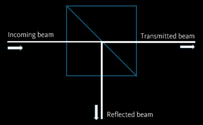
If one directs a laser beam on a prism, a fraction of beam power will be reflected. The other fraction will be transmitted to the other side. As the direction of those reflected and transmitted beams differ from the incoming beam, the momentum and force associated with the beam changes.
The behaviour of the laser beam can be described using geometrical/rays optics, as long as the objects are much larger than the wavelength of light. This approach is valid for typical optical trapping in biology applications, where objects are around the size of one micron or larger.
1.1. Optical Rays
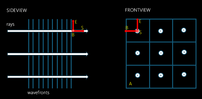
As you can see from the image, the light rays are perpendicular to the electromagnetic wavefronts (E and B) and pointing in the direction of energy flow (S).
S (energy flux density due to an electromagnetic wave) = Number of photon passing through single unit area (A) per unit time multiplied by energy per photon.
P (power of each ray) = S A
When a light ray hits on a flat surface between two media with different refractive indices, it is reflected and transmitted. The angle of the incoming light with respect to the line normal to the surface is called the angle of incident (θi). According to the law reflection, the angle of reflection (θr) = the angle of incident.
The Snell’s law states that the angle of transmission (θt)
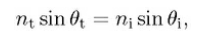
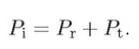
The incoming optical power must be equal to sum of reflected and transmitted optical power.
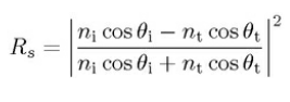
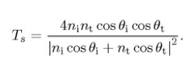
The splitted power between the reflected and the transmitted rays is dependent on the polarisation of the incoming ray. They are expressed by so called Fresnel’s equation. For s-polarised ray (electric field E is normal to the plane of incidence),
the intensity reflection coefficient,
the intensity transmission coefficient.
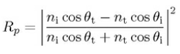
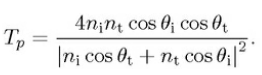
For p-polarised ray (electric field E is paralel to the plane of incidence),
the intensity reflection coefficient,
the intensity transmission coefficient.
For unpolarised or circularly unpolarised, the intensity reflection coefficient R = (Rs+Rp)/2, the intensity transmission coefficient. T = (Ts+Tp)/2.
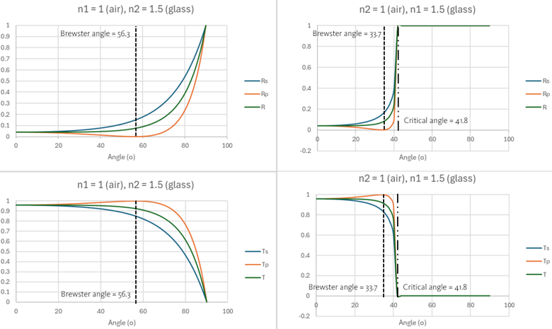
This plot shows the values of intensity reflection and transmission coefficient of s-polarised (perpendicular polarisation or TM (transverse magnetic)) and p-polarised (parallel polarisation or TE (transverse electric)).
On the left hand side, the incoming ray goes from air to glass. The upper one shows reflection whereas the lower one shows transmission. On the right hand site, the incoming ray goes from glass to air.
In the air to glass scenario, the transmission of s-polarised ray (Ts) only decreases as the incidence angle increases. For the p-polarised ray (Tp), the transmission increases until the incoming light reaches the Brewster angle (56.3 degrees). Beyond it, the transmission decreases.
Interestingly, in the glass to air scenario, the transmission of both s- and p-polarised ray fails starting at the critical angle. This is known as total internal reflection. The maximum transmission of the p-polarised ray appears at the incoming angle of 33.7 degrees.
Brewster angle = arctan(nt/ni)
Critical angle = arcsin(nt/ni) *only when light goes from higher to lower ref. index
1.2. Optical forces
A photon carries energy and momentum. When a photon is elastically scattered (i.e., the total kinetic energy remains constant) by an object, the momentum can change thereby generating a recoil force on the object stated by the momentum conservation law.
1.3. Scattering and gradient forces.
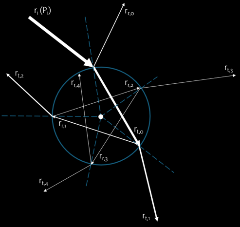
Forces acted on a trapped microparticle (high refractive index compared to the surrounding) can be described using a minimal model shown in the image (ray scattering on the plane of incidence). The force caused by a single ray ri of power Pi hitting the particle at an incident angle. The majority of the ray will be transmitted (rt,0), while just a small amount will be reflected (rr,0). Inside the particle, the ray will be travel across until it hits the interface. Again, most of the ray will be transmitted (rt,1), while just a small amount will be reflected (rr,1). The scattering event will continuously repeat until the ray escapes from the particle.
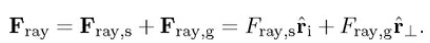
Total force of a single ray acting on the particle
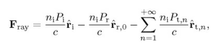
Remember, the image only showing the scattering events only on two-dimensional plane of incidence. Therefore, the total force of a single ray has only components in the plane of incidence. In reality, the particle is three-dimensional sphere. The total force is a combination of the scattering force (i.e., force pushing the particle parallel to incoming ray) and the gradient force (i.e., force pulling the particle perpendicular to the incoming ray).
Optical Trapping
Due to the scattering force, we cannot trap a high ref. index particle just using a single ray. In principle, having a second counter propagating ray is possible to create an optical trap. The modern approach employs the counter propagating ray arranged at a certain large angle. Even more convenient method is to use a focused light beam from a high numerical aperture lens.
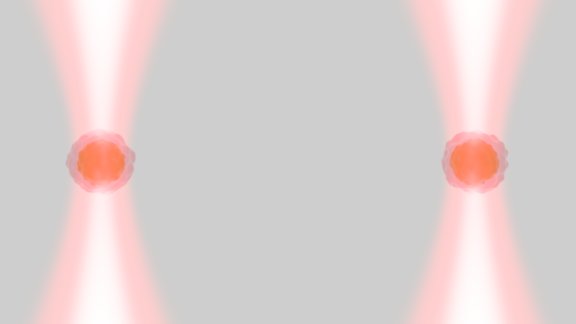
It is also possible to trap low refractive index particle by employing a hollow/doughnut beam profile (i.e., Laguerre-Gaussian beam) instead of the typical Gaussian profile.
Quantitative Force Measurement using Optical Trap
Interferometry Method
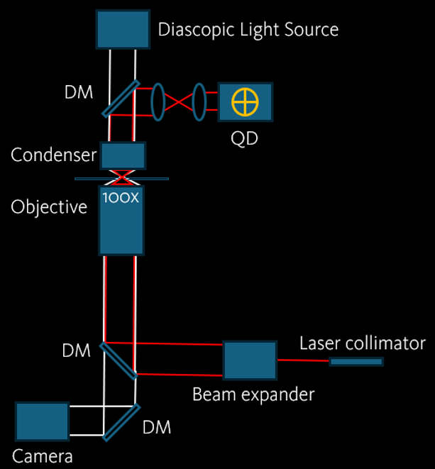
The detection of interferometric position relies on the superposition of incoming light and scattered light caused by the trapped particle. This will generate an interference pattern that will be collected by the condenser. A high speed and high precision quadrant photodetector is then placed at the conjugated plane of the condenser back-focal plane. The bead movement will be recorded as change in voltage. In the end, the trap stiffness and forces can be calculated by power spectrum analysis.
Imaging Method
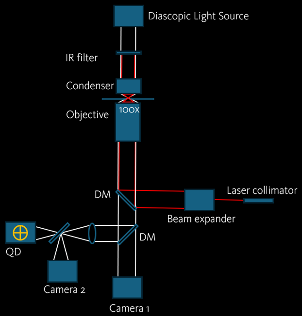
In this mode, the image of the trapped bead is analyzed with a quadrant photodetector that is mounted on a camera port. The determination of the trap stiffness and forces is done by measuring the phase shift of the trapped bead at various oscillation frequencies.
Applications
1. Measuring forces acting on a trapped bead caused by liquid flow in microfluidic chamber.

2. Measuring pulling force on a filament attached to the glass surface.

3. Measuring bead-cell interaction force.

4. Investigating neuronal chemotaxis through the optical manipulation and disruption of liposomes (Combined Optical Tweezers and Laser-Microdissection)
Pinato et al. Neuronal chemotaxis by optically manipulated liposomes. J. Eur. Opt. Soc.-Rapid Publ. 2011
References
- Optical Tweezers – Principles and Applications. 2015. Philip H. Jones, Onofrio M. Marago, and Giovani Volpe. Cambridge University Press.
Which solutions does MMI offer for Optical Trapping?
The MMI CellManipulator optical trapping system enables comfortable, ultra-precise and contact-free manipulation of microscopic particles, single living cells, or subcellular organisms and the measurement of intracellular activities. The Optical Trapping system can hold, move, rotate, join, separate, stretch or otherwise manipulate up to 2 x10 microscopic objects simultaneously or separately in three dimensions. The wavelength of the laser does not interfere with the integrity of living specimens.
Quantitative force measurements can also be accomplished with the quadrant detector enabling the measurement of binding forces or viscosities at sub-cellular level. Automated quadrant detector calibrations routines allow force-distance measurements, so called Force Spectroscopy.
The MMI CellManipulator Optical Trapping system is highly modular and can be mounted on numerous microscope brands from entry level, mid-range to high-end instruments. The MMI CellManipulator can also be flexibly combined with all other MMI tools, such as the MMI CellEctor to selectively isolate single cells, or the MMI CellCut for precise laser microdissection. In addition, the MMI CellManipulator can be integrated with Raman microscopy and other manipulation system such as a microfluidic chamber to build so called Optofluidic Raman-activated Cell Sorter. Please contact us to configure your customized system.
Research Articles Featuring MMI Optical Trap
Koenig et al. Time-gated autofluorescence microscopy of motile green microalga in an optical trap . Time-gated autofluorescence microscopy of motile green microalga in an optical trap.1998
Michael Eisenstein. Cell sorting Divide and conquer. Nature. 2006
Andersson et al. Using optical tweezers for measuring the interaction forces between human bone cells and implant surfaces: System design and force calibration. Review of Scientific Instruments. 2007
Lee et al. Construction and calibration of an optical trap on a fluorescence optical microscope. Nature protocols. 2007
Sparkes et al. Grab a Golgi: Laser Trapping of Golgi Bodies Reveals in vivo Interactions with the Endoplasmic Reticulum. Traffic. 2009
Hawes et al. Optical tweezers for the micromanipulation of plant cytoplasm and organelles. Current Opinion in Plant Biology. 2010
van der Honing et al. Actin and myosin regulate cytoplasm stiffness in plant cells: a study using optical tweezers. New Phytologist. 2010
Zhou et al. The biomechanics of drug-treated leukemia cells investigated using optical tweezers. Nano LIFE. 2012
Zhou et al. Hepatitis B surface antigen–antibody interactions studied by optical tweezers. IET Nanobiotechnology. 2012
Ng et al. Frequency-dependent cell death by optical tweezers manipulation. Journal of Cellular Physiology. 2013
Ketelaar et al. Optical Trapping in Plant Cells. Plant Cell Morphogenesis. 2013
Legres et al. The laser technology: new trends in biology and medicine. Journal of Modern Physics. 2014
Khakshour et al. Mechanical characterization of ART-treated Jurkat cells using optical tweezers. 2014 36th Annual International Conference of the IEEE Engineering in Medicine and Biology Society. 2014
Zhou et al. Accurate measurement of stiffness of leukemia cells and leukocytes using an optical trap by a rate-jump method. RSC Advance. 2014
Hoppens et al. Ceragenin Mediated Selectivity of Antimicrobial Silver Nanoparticles. ACS Publications. 2014
Khakshour et al. Probing Mechanical Properties of Jurkat Cells under the Effect of ART Using Oscillating Optical Tweezers. PLOS ONE. 2015
Zhou et al. Mechanical oscillations enhance gene delivery into suspended cells. Scientific Reports. 2016
Lapin et al. MINDEC-An Enhanced Negative Depletion Strategy for Circulating Tumour Cell Enrichment. Scientific Reports. 2016
Quadt et al. Coupling of Retrograde Flow to Force Production During Malaria Parasite Migration. ACS Nano. 2016
Adur et al. Multimodal and Non-Linear Optical Microscopy Applications in Reproductive Biology. Microscopy Research and Technique. 2016
Steinbusch et al. Sex-Specific Control of Fat Mass and Counterregulation by Hypothalamic Glucokinase. Metabolism. 2016
Khakshour et al. Retinoblastoma protein (Rb) links hypoxia to altered mechanical properties in cancer cells as measured by an optical tweezer. Scientific Reports. 2017
Lee et al. An automated Raman-based platform for the sorting of live cells by functional properties. Nature Microbiology. 2019
Lee et al. Raman-based sorting of microbial cells to link functions to their genes. Microbial Cell. 2020.
Lee et al. Optofluidic Raman-activated cell sorting for targeted genome retrieval or cultivation of microbial cells with specific functions. Nature Protocols. 2020.
Asgharsharghi et al. Optical trapping and force spectroscopy of non-spherical rod- shaped bacteria and diatoms. MMI App. Note. 2022.
Ripp et al. Phosphorylation of myosin A regulates gliding motility and is essential for Plasmodium transmission. EMBO reports. 2022.
Hammell et al. Molecular-level evidence of force maintenance by smooth muscle myosin during LC20 dephosphorylation. Journal of General Physiology. 2022.
Ling et al. A Novel Step-T-Junction Microchannel for the Cell Encapsulation in Monodisperse Alginate-Gelatin Microspheres of Varying Mechanical Properties at High Throughput. Biosensors. 2022.
Lyu et al. Advanced glycation end-products as mediators of the aberrant crosslinking of extracellular matrix in scarred liver tissue. Nature Biomedical Engineering. 2023.
Riva et al. Identification of inulin-responsive bacteria in the gut microbiota via multi-modal activity-based sorting. Nature Communications. 2023.
Wu et al. Gelatin-based 3D biomimetic scaffolds platform potentiates culture of cancer stem cells in esophageal squamous cell carcinoma. Biomaterials. 2023.
Dorta et al. Optical tweezers to measure the elasticity of red blood cells: a tool to study the erythrocyte response to antimalarials. Frontiers in Malaria. 2024.
Dorta et al. Mechanical Characterization of the Erythrocyte Membrane Using a Capacitor-Based Technique. Micromachines. 2024.
Wang et al. Polymerization of Tspan7 into Helical Transmembrane Skeletons for Membrane1 Tether Stabilization. bioRxiv. 2024.

“The MMI CellManipulator Plus optical trapping system was customized on an upright microscope upon our request. The tweezer has been working reliably, with excellent manipulation power and flexibility on various devices, from simply glass slides to microelectrodes on silicon. The MMI service was also professional, fast and considerate.”